| |
Read all of the instructions
before starling the assembly |
| |
|
| 1 |
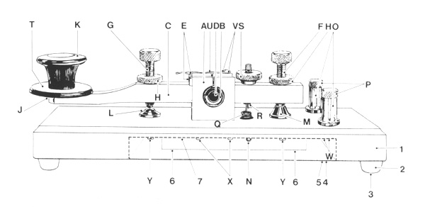
On the base loosely fit the front silver tipped contact
(L) using a short 4mm screw having first placed a solder
tag and a washer under the screw head. |
| |
|
| 2 |
Loosely fit the rear brass stop (M) using a short
4mm screw and washer. |
| |
|
| 3 |
Take the bearing block and arm assembly and fit screws
(F) and (G) together with the knurled locking nuts (H)
(Note the tipped screw is at the front) and allow the
screws to protrude underneath by not more than 3mm.
Fit the plastic knob (K) and skirt (T) using the brass
mounting stud. Do not allow the stud to protrude underneath. |
| |
|
| 4 |
Loosely fit the bearing block assembly using the four
3mm screws and washers having first placed a 3mm solder
tag under any one of the screw heads |
| |
|
| 5 |
Align the front contacts and rear stops then tighten
all the screws. At this stage check that the top and
bottom contacts and the rear stops are correctly aligned.
If necessary, make adjustments to ensure correct alignment. |
| |
|
| 6 |
Fit the two terminal posts (0) and screws (P) using
4mm screws, having first placed solder tags and washers
under the screw heads. |
| |
|
| 7 |
Solder a short length of wire between:-
(i) The front contact solder tag and any one of the
terminal posts solder tags.
(ii) The bearing block solder tag and the second terminal
post solder tag. |
| |
|
| 8 |
Cut the length of the braided wire to approximately
65mm long then solder each end to a 3mm solder tag and
fit to the bearing block and arm using the 3mm brass
screws (V) |
| |
|
| 9 |
Taking care to protect your eyes, attach spring (0)
to brass stud (A) then pass the stud through underside
of base into the brass arm, securing with steel retaining
pin (N) on the underside and knurled brass adjusting
nut (S) on top. |
| |
|
| 10 |
Position the two steel weights (6), one on each side
of the base cut out, securing with the two csk wood
screws. |
| |
|
| 11 |
On the steel cover plate attach the self -adhesive
green baize strip and trim off surplus with a sharp
knife or scissors (Note: take care not to damage table
fop and fingers if using a knife) |
| |
|
| 12 |
Locate the steel cover plate centrally on the base,
then secure with the four round head wood screws and
rubber feet, having first placed a 3mm washer in the
recess of each of the rubber feet. The screws should
be located in the four pre-drilled pilot holes. |